
By:Dr. Robin Tuluie, Ph.D.
As I've set out to cover a large part of motorcycle technology - more or less everything to do with motorcycle chassis technology - and I think it is quite important to clearly define all the terminology and geometry right from the start. As you will see there are not a lot of definitions, but a clear understanding of these basic terms is essential for an understanding of what's to follow.
First there are the geometrical definitions. These dynamical measurements determine how the bike behaves while being ridden.

Sometimes the top and bottom triple clamps do not have the same offset. In that case the trail and wheelbase (but not the rake!) are altered. Also, if the center of the front wheel axle is not in the center of the fork tube as viewed from the side of the bike, then this is equivalent to a change in the offset (and thereby the trail) of the bike.
Begin by placing the bike on it's center stand, or better yet, support it via wood or stone blocks from both sides as per figure 3.

Put a drop line - which consists of about 2 feet of your brightly colored sewing thread with a weight (a small nut, for example) tied on one end - on the top edge of the rear tire and a little backwards so that it clears the axle and swingarm. Depending on which side of the tire you've put the string, there will be a small gap between the bottom tire edge and the string. For later reference, call this gap `a_r'. For now, adjust the blocks under your bike so that this gap is small, say less than 2 mm. This doesn't have to be accurate yet. Now you've got the bike nearly vertical. Make sure the bike is secure as you'll be doing a lot of measuring and moving around and you don't want the bike to move during this. Turn the steering wheel so it points straight ahead approximately (we'll get it perfectly straight later).
Next string some thread from the back of the rear tire around the front tire and back to the rear tire again (see figure 1 again, posted below). Make sure that the string isn't touching anything else besides the tires! If it's touching the center stand or exhaust you'll need to move the string up or down along the tire. The higher up along the tire you can get the string, the better, but typically the highest one can get is maybe eight inches off the bottom of the tire before the string hits the brake disk or bottom of the engine. At worst, you'll have to remove some parts to gain the necessary clearance. Next straighten the front wheel by adjusting gap `b' in figure 1 to be the same on the left and right side of the bike. Measure the width of your rear tire and cut a piece of wood to this length (I find that a pencil works great for this). Now stick this pencil between the strings, just behind the front tire and perpendicular to the strings. The strings should be nice and tight and hold the pencil in place. If not, tighten the strings and use a piece of duct tape to hold the pencil against the front tire.
Now go back to the rear wheel and look down along the strings: Usually one string will be closer to the front edge of the rear tire than the string on the other side. Adjust the chain adjusters (take the chain off before) to move the rear wheel so that the gap `c' is the same on both sides. If the pencil is exactly the same length as the width of the rear tire, the gap `c' will be zero on both sides. Now go back to the front wheel. Remove the pencil and check whether gap `b' is still the same on both sides. If not, turn the steering wheel ever-so-slightly to make `b' the same on both sides. Stick the pencil back in (make sure it goes in symmetrically, so that it sticks out the same amount on each side), and recheck the alignment for the rear wheel. You may have to adjust the chain tensioners just a tad now, but once you've done this you're done with Part (1). Your wheels are now in-line!
Now that your wheels are aligned, be very careful not to bump into the bike. Any slight perturbation of the motorcycle can move the handle bars and throw off all your previous work.
Next we'll do an easy, preliminary check to see if the frame and swingarm of the bike are not twisted, which the most common type of damage.
With the wheels aligned, put the drop line on the rear tire just as before, and measure gap `a_r' just as before. Also measure distance `s_r' in figure 3.
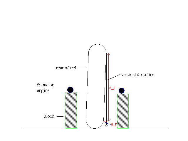
If the string touches on one side of the tire on both the top and bottom, move to the other side. There should be at least a small gap now. If not, the bike is perfectly vertical, so record a_r=0. Note that the bike doesn't have to be perfectly vertical! Don't attempt to readjust the bike to get a_r=0, it will only disturb the wheel alignment. Whether a_r=0 or not, it will not affect the accuracy of the measurement we're about to take. Next go to the front wheel and record a_f and s_f there.
It helps if s_r and s_f are the same. If this is not possible for your bike (it should be, though, follow part 2 (b) below). If s_r and s_f are the same, then take the difference and divide by s_f. This gives the angle theta by which the wheels are out of plane:
theta = 57*(a_r -a_f)/s_f
(b) if s_r and s_f are not the same:
theta = 57*(a_r/s_r - a_f/s_f)
Here the coefficient 57 is just the conversion factor form radians to degrees. It also doesn't matter what units you use for a_r, a_f and s_f, as long as they are all the same (i.e. either mm, cm or in, but no mix of them). This formula is the small angle approximation for sin(theta) and tan(theta) and valid here for angles less than approximately 5 degrees, which will always be the case here.
In fact, your value of theta should be between 0.0 and 1.5 degrees. If theta=0, then both wheels are in plane and most likely your chassis is perfectly straight. If theta is less than 1.0 degree, your chassis is not quite straight, or your wheel not properly spaced (in the swingarm), or your forks or swingarm are bent. However, if theta is no more than 1 degree, the "tweak" in your chassis is minor and will most likely be acceptable, even for racebikes. Sandy Kosman once told me that they usually don't bother to straighten a bike unless theta is greater than 1.5 degrees, and my own experience with straightening frames and building chassis has shown this to be true.
Now, if you're a world-class racer and really good at picking up even the slightest chassis imperfections you'll probably notice theta=0.5 degrees. However, as long as theta is about 1.0 degree the chassis will be aligned well enough for most mortals. If theta is considerably larger than 1.5 degrees then either you've goofed somewhere along the line of this measurement or you've got a problem. I suggest re-checking the entire process, including the wheel alignment, as it is easy for the strings to hang up or touch against something and throw off your entire measurement. If you still have theta considerably larger than 1.5 degrees you'll need to find out what's wrong with your bike.
Similar to the method we used previously to align the rear wheel relative to the front wheel, we will now align the sprockets. It should be clear that if the wheels are aligned, the swing arm and frame straight and the sprocket offset and rear wheel spacers correct, then the sprocket alignment will be true. However, for many custom built bikes using different wheels and spacers, relaced spoke wheels or different sprockets this may no longer be the case. I've found that especially on older Vintage machinery often the rear axle adjustment at which the wheels align does not coincide with the adjustment at which the sprockets align. Older Vintage machinery has often been subjected to several previous owners and one is never quite sure what is original and what has been replaced. Even newer machines with cast wheels can suffer from sprocket misalignment if the wheels are not OEM-spec, aftermarket sprockets or wheel spacers are used or a bent swing arm is suspect.
Remove the chain from the motorcycle and chain guard and front sprocket case cover if necessary. Referring to figure 1b below, simply string a line from the front sprocket to the rear one. Align the line at the rear sprocket as shown. If the sprockets are aligned, then this line should just graze the edge of the front sprocket. Make sure that the line is straight.

If this alignment cannot be achieved, then assuming you have previously aligned the wheels as in Part 1, the logical conclusion is that the rear axle adjustment which yields proper sprocket alignment is not the same as the rear axle adjustment which yields true wheel alignment. Hence something is wrong. First check that the rear sprocket offset is correct. Do this by comparing to the correct OEM wheel and sprocket assembly.
The next step is to look at the chassis itself an determine if the frame, forks or swing arm are straight. This step is also the next step if a proper wheel alignment results in the wheels being out-of-plane as in Fig 2 of part 1 of our article. Just because the wheels and sprockets align doesn't mean that the chassis is straight - the wheels must be in a single plane as well (as described in part 1). Referring to figure 3 of Part 1, this means that the angle
theta = 57*(a_r -a_f)/s_f
should be close to zero (plus/minus 1 degree). If it is not within this spec, then the chassis needs fixing.
So let's suppose that somehow your chassis alignment and sprocket alignment don't agree and/or the front and rear wheels are out of plane. After all, if they do agree (to within the limits of accuracy stated above), then you're home free, your wheels and sprockets aligned and both wheels in the same plane. At that point, there is little reason to suspect a bent chassis unless several parts are bent and conspire to give aligned (which also means "in plane") wheels and sprockets - a somewhat unlikely scenario!
The first check is to see if any of the axles are bent: either roll them on a flat surface or hold a straight edge along them, turning the axle in the process to at least two different spots. The next check is to see if the swing arm is bent. The most common way for the swing arm to be bent is a twist in the cross tube - imagine standing behind the bike, taking hold of the swing arm legs and pushing one down and the other up. This would result in a twist of the cross tube. An easy way to discern this without dismantling anything is as follows: Referring to figure 2, and with the sprockets and wheels aligned (or as close to it as possible with the suspect bent chassis), get the rear wheel vertical to ground, using a carpenters level or the string method. Next see if the swing arm axle is horizontal - you can do this by either feeding a string or straight rod through the swing arm axle (if hollow) and holding a level along the string, or by measuring the distance d1 and d2 of figure 2 from the axle center to either a flat and level ground or to a carpenter's level that is set up on the ground in a horizontal position, perpendicular to a line connecting the front and rear tires.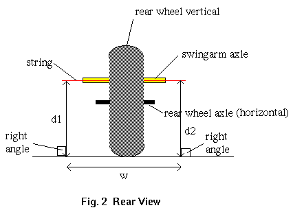
Part 6: CHECKING THE FRAME
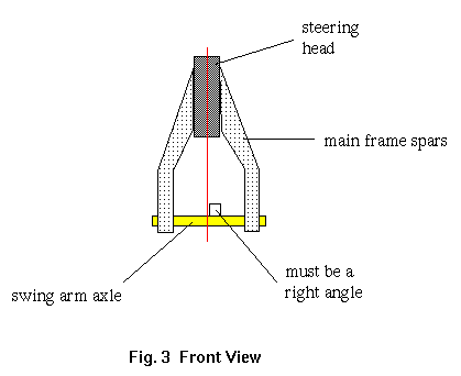
Figure 3 shows that the steering head must lie in a plane normal -- that is perpendicular -- to the swing arm axle. It is not generally required that this plane intersect the swing arm axle in the center of the axle, 1/2 way between the frame spars. Some machines have asymmetrical frames with respect to the center of the swing arm axle. However, in all cases, the steering head MUST lie in a plane normal to the swing arm axle. In addition, for a perfectly aligned chassis, the steering head must lie directly vertically above a line connecting the center of the tire contact patches when the wheels are aligned and vertical.