Valve Adjustment
By:crwmac
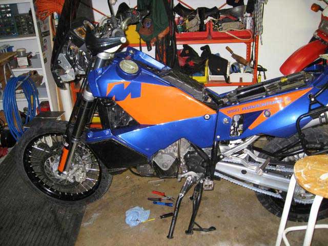
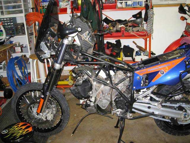
This is my first time to do a valve adjustment on the 950 so this is only a documentary of that exercise. Use this information at your own risk. I followed the manual closely and used lots of information gathered on this forum not the least of which were the many helpful posts and suggestions.
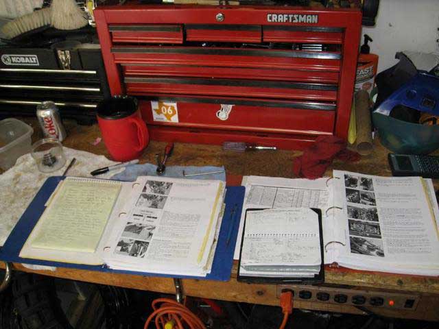
My reference material included a hard copy of the service manual, a separate manual that I have compiled with information from forum posts by other inmates, a list of items to accomplish with this service, and a writing tablet to record each step as I go. I will use the step-by-step record to re-assemble things in reverse order.
Since I will also be doing an oil change, I first removed the side covers, seat, glove box and skid plate.
Next, I warmed the engine so the oil will drain completely, then removed the left crash bar and tank (see my tank removal blurb below). After the left tank was removed, I drained the oil from the case and the oil tank, removed, cleaned and replaced the screens, and replace drain plugs using new copper sealing washers. This procedure is well described in the manual.
Then I remove the right crash bar and fuel tank.

The fuel tanks are each secured with three Allen head bolts. Each side is the same. I always loosen the top bolt first, this takes shear tension off the lower bolts. Then, I removed the lower front bolt, removed the other two crash bar bolts and removed the crash bar. Then, I removed the rear attachment bolt. I am careful not to loose the rubber and aluminum shims at each tank attachment.
With the top front tank bolt loose, but not removed, I can pull the lower portion of the tank away from the frame to access and disconnect the vent hose and the gas gauge electrical connector (gas gauge connector on left side only).
At this stage, I turned off the fuel valve(s) and disconnected the fuel line at the bottom of each tank (two on the left side, one on the right). It is almost essential to pull the tank away from the frame to remove the fuel line that connects the two tanks. The skid plate assembly is really too close to the connecting hose fuel attachment. We need a little more room there, KTM.
With each step of disassembly, I cleaned newly exposed parts of the motorcycle. I want things as clean as possible when I expose intakes and open valve covers.
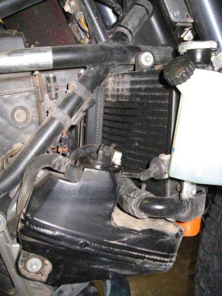
Next, the manual says to remove the radiator bolts and slide the radiator forward to gain more front cylinder access. This did not give adequate working room, so I drained the coolant and removed the radiator.
Radiator removal is very straight-forward. I drained coolant as per the manual. I disconnected the hoses, the screen, and the four mounting bolts. I also disconnected the thermostat switch at the right rear of the radiator and as I was able to lean the radiator forward, I unplugged the fan. This electrical plug has a little clip that has to be pressed to unlock the plug allowing it to be removed. I was careful handling the radiator since the fins are easily damaged. I took this opportunity to clean the radiator by blowing out the fins from the rear side alternately with compressed air, and water from the garden hose. While my bride was out shopping, I used the kitchen sink with that handy little hand sprayer she thinks is only for dishes. Unknowingly, I dripped a little coolant on the kitchen floor. Later when she discovered it and asked what it was, I quickly employed my adorable routine. Playing dumb, I wiped up the spill, and scurried off to the garage. It worked! …I OWN that woman!
Next, I lifted the carburetors and air box out of the way for good access to the valve covers.
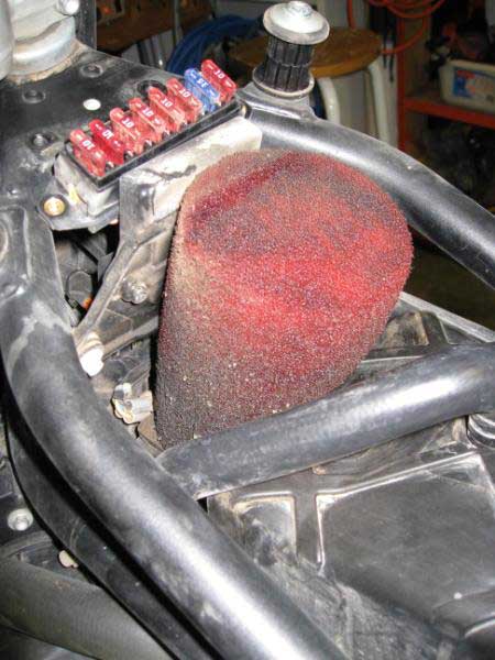
First, I remove the air-box cover, carb horns, air filter, and, in my case, the Uni pre-filter (which works great, by-the-way; I didn’t have to change any jetting or adjustments for this item). The pre-filter greatly extends main filter life. Look how dirty it was.
Next, my goal was to lift the two carburetors and air box out of the way as a unit without disconnecting cables. The unit can be lifted, pivoting on the cables entering the front of the air box and then bungee-strapped as an assembly, to the handle bars.
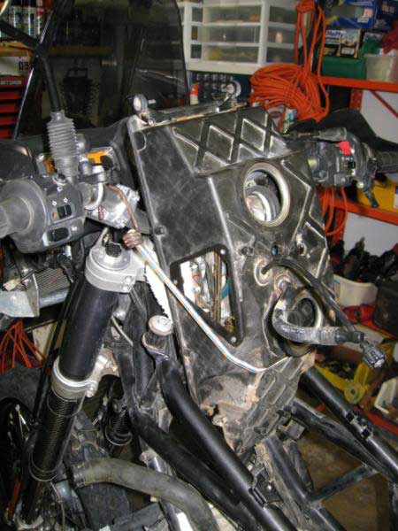
Here's how I did it: I disconnected the air box drain tube (under left side). I disconnected the fuel line that leads to the carbs at the joint on the left side (now exposed with the left tank removed). I removed the triangular covers on both sides of the lower air box.
I could have probably removed only the right side triangular cover, but removing both gave me more access and allowed me to more easily see what I was doing. The carbs connect to the intake manifold through two large holes in the bottom of the air box. Each air box hole is lined with a grommet that fits tightly over the respective manifold allowing the manifold to extend into the air box.
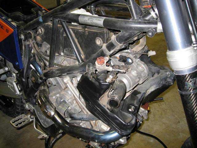
Here you can see the side access, and the fuel line, and the idle adjustment coming out of the bottom of the box. You can also see plenty of Big Bend Texas dirt road dust.
A separate grommet connects each carb to each manifold. This grommet has two hose clamps. The upper clamps the grommet to the carb. The lower one clamps the grommet to the manifold.
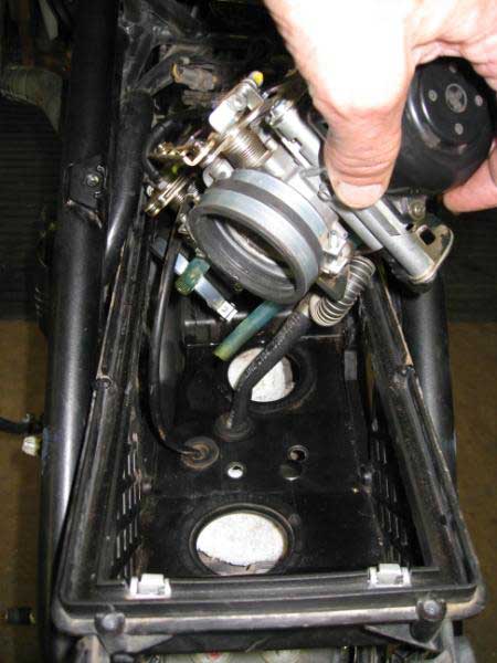
Reaching in through the right side triangular hole (with a 6mm hex driver), I loosened the two lower clamps. I then lifted the carbs and lower air box off the manifolds. The grommets fit snugly so I carefully worked them loose until I could lift the box and carbs. The air-box grommets fit snugly too. Once loose, I lifted the whole assembly forward and bungeed it to the handle bars. The idle adjustment cable will also remained attached. I just cleared the cable and idle adjustment knob so it could follow the assembly as I raised it.
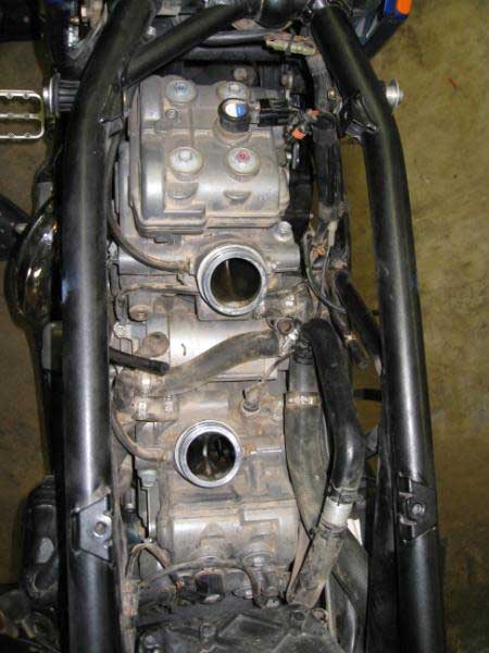
I stuff rags into the intake manifolds to keep them clean. Engine holes are dirt and tool magnets. I covered the manifold intakes with rags to keep them clean and to elude Murphy’s Law which clearly states, whenever there is an opening into a critical component, you WILL drop something into that opening. Here’s a picture before I blocked the openings.
I found all of the carb/air box parts were very sturdy including all of the carburetor connections. I didn’t find any of this work difficult. It does take some time. Rushing work like this is a bad thing anyway.
Next, following the manual and my notes, I remove the two oil line connections from the front valve cover and removed the spark plug coil electrical connectors. Then I pulled out the ignition coils. These coils are a pressure fit. They do not screw or lock in place. They simply pull out. However, they are plastic and were in tight enough that I worried that my pulling and wiggling might break them. They finally came loose with some gentle twisting. Then, I removed the spark plugs using the tool from the on-board kit.
Next, I removed the rear valve cover with gasket, being careful with the gasket, making sure that it did not try to stick to the cylinder and distort or break. It came off very easily. This gasket looks like very sturdy thick plastic.
I followed the procedure in the manual to place the rear cylinder at top-dead-center and locked the crankshaft in this position. Others have suggested turning the engine by rotating the rear wheel in sixth gear. This didn’t work for me. The rear wheel, even in sixth gear was too hard to turn. I did as the manual described, I removed the plug in the generator cover and used a 14mm Allen wrench to turn the engine. The engine turned very easy with the spark plugs removed. Finding TDC is a no-brainer. I just aligned the marks on the cam gears as described in the manual and made sure that the cams are facing as described in the manual, all rear cylinder cams facing in for rear TDC, and all cams facing out on front cylinder TDC. Then using the locking tool (screw), I locked the engine in place. Next, I removed the spark plug shaft insert. Next time, I may not do this but it looked as though if I didn’t, I might damage the insert while accessing two of the cam bridge screws that are very close to the insert. The plug shaft is an o-ring pressure fit. I carefully pried from both sides with two straight slot screwdrivers and it surrendered easily.
It’s so cool being inside the engine like this. It makes me feel …well …smart. I frequently called my wife to the garage to show her the inner workings, and as I feigned complete confidence, described to her what I was doing. It’s also cool when she thinks I’m smart. However at this point, she was probably wondering how much it would cost to repair the impending disaster, even if it could, in fact, be repaired.
See those white spots by the cams in the picture below? They look a little odd. I can’t imagine any purpose. I think that area is just a rough part of the metal cam left over after milling.
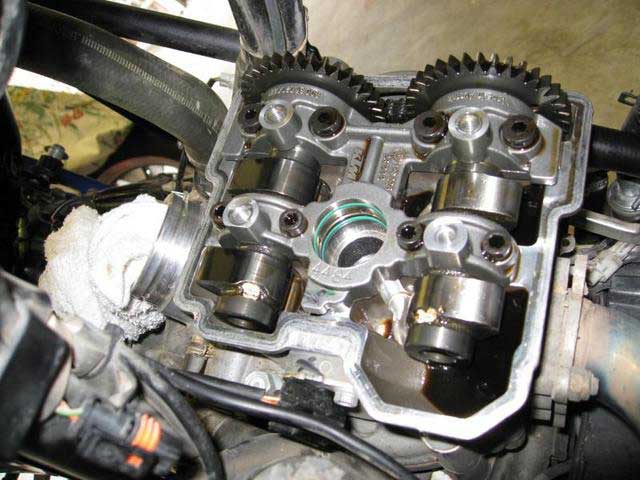
In the picture above, you can see the eight cam bridge bolts, the cam bridge, the green O-rings that seal the now removed spark plug shaft insert, cams, and cam gears. Timing marks (not visible) are on the left side face of the gears. That way, when looking for TDC, I could see the marks from the left side, where I needed to be to turn the engine over. Those KTM engineers thought of everything! At TDC each gear’s timing mark aligned with the smooth outside edge of the cylinder top where the cover gasket will seat. If you look closely, you can also see tabs that stick out from points on the cam bridge. I found these tabs to be handy places to wedge a finger for prying off the bridge after removing the bolts.
I deviated from the manual at this point to follow advice by CP, and other inmates. It has been recommended that this opportunity be taken to re-torque the head nuts. Starting with the rear cylinder, I checked the existing valve clearance with a feeler gauge and noted the gaps.
(ed. Let the engine cool down completely before doing valve clearance checks. As the engine heats up, the clearances will decrease. Three to four hours is sufficient on a water cooled, overhead cam engine such as the LC8, though longer will not hurt.
Note1: 2003-2004 engines use Intake 0.10 – 0.18 mm
and Exhaust 0.23 – 0.31 mm
Note2: 2005 and later engines use Intake 0.10 – 0.15mm and
Exhaust 0.25 – 0.30mm)


KOTH: Here's a handy Excel spreadsheet that will calculate your shim sizes.
Then, with all miscellaneous openings covered with clean rags, I removed the cam bridge screws. The cam bridge is a very precise fit and has to be pried loose after all the screws are removed. I did this with my fingers only as mentioned above. Then I again studied the timing marks on the cam gears so I could remember exactly how they aligned, and removed the cams.
According to inmate wisdom, there are six nuts on each cylinder that should be checked. Four are actual head nuts that receive full torque in two stages. First, tighten to 25Nm then, in the second stage, to 38Nm. The other two are nuts on the side of the cylinder and honestly I don’t know how important they are, but I checked them too. I read on the forum that the actual purpose of these two nuts (only tightened to 8Nm) is for alignment or something during engine assembly. Referring to the engine assembly section in the manual and combining that with inmate advice, here is the procedure I used for tightening all of these nuts.
I loosened each nut one at a time and re-torque that nut before proceeding to the next. The object was to tighten the nuts without disturbing the head gasket which is securely in place and not blown. I didn’t want to do anything to change that. I started with one of the two inside nuts, the ones under the cams. Then I moved to the large outside nut on the outside of the cylinder working “crosswise” as per the manual. One-at-a-time, I loosened, lubed with engine assembly grease or oil (as per the engine assembly section of the manual), and re-torqued each nut to 25Nm. Next, for the two small nuts on the same side of the cylinder but not under that valve cover (see manual), one-at-a-time loosen and re-torqued to 8Nm. One of the high torque outside nuts will require a torque wrench adapter. I use a handy clamp by motion pro that allows the use of any box end wrench (or anything else) as an extension to a torque wrench
http://www.motionpro.com/motorcycle/tools/adjustable_torque_wrench_adaptor/
If you use the attachment at 90 degrees from the torque wrench, no adjustment of the torque value is required. Then, tightening crosswise, I tighten each nut that was previously set to 25Nm to 38Nm.
Now for the buckets and shims. These items were previously a source of great mystery. I could visualize what a shim is but what is a bucket and what is a bucket doing in a motorcycle engine? Now I know (sooo cool). Looking at the cylinder top with the cams removed you see the bottom of the buckets. They are turned upside down.
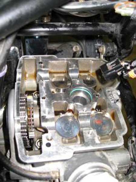
In this picture you can see the two inner head bolts. The cams are removed and you can see the buckets turned upside down and in place over the top of the valves. The shims are under the buckets.
The buckets fit down over the top of the valve stem and cover the shim which sits on the top of the valve stem. On the stem top there is a little raised ring that cradles the shim, keeping it in place. I used a magnet to remove the buckets. I simply touched the magnet to the bucket and pulled it out. Sometimes the shim came out stuck to the underside of the bucket. Sometimes the shim stayed in its little cradle on top of the valve stem, and other times the shim attempted to jump into one to the adjacent openings that I had so carefully blocked with clean rags. When a shim didn’t come out with the bucket, I simply picked the shim up with my fingers or reached back in with the magnet. I found this all very easy.
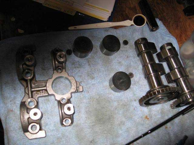
In the above photo you can see the cam bridge, buckets (open side down, the way they are installed), the little shims, and the cams.
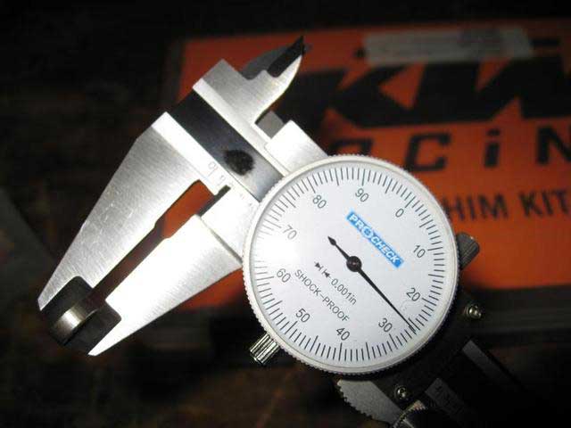
Resetting the valve clearance is very straight-forward. Fortunately, I have the entire shim kit. A friend and I went together on the kit to avoid the trouble of trips to the dealer for individual shims. The shim kit comes in size increments of .05mm. Each shim in the kit is stamped with its size (in ink). Shims removed from the engine were not marked with a size (probably worn off) and had to be measured. I used a vernier caliper to measure these. Yeah, it’s in thousandths. I made myself an easy chart to convert quickly from thousandths to corresponding shim size in mm’s.
(ed. Record these measurements and save for reference during future cam clearance adjustments.)
Notice that the valve clearance specification for intake and exhaust have only a .05mm range. This means that most of the time there is only one shim size that will put you within specification. The only other possible condition is that you are on the edge of the range, barely in-spec, i.e. at .10mm on an intake clearance. If that were the case, the next smaller shim would put you at .15mm, the other edge of the range. My dealer advised me to go with the larger clearance in this case. Therefore, one really does not have any choice of where they fall in the range. As much as I would like to, I could not adjust perfectly to the middle of the range.
As I worked to adjust the first set of valves, I realized it is very easy to determine the correct shim size. I’m a little slow. Of course, if the clearance is in-spec, no shim change is needed. If the range is out of spec, less than .05mm, then the next size shim is required. Of my 8 valves, two were in spec, one gap was too small, and the other five were too large. I have also been told that as valves wear, the clearances get smaller, they do not get larger. The only way you should find too large a clearance is if it were set too large at the last service ...hummmmm. I don’t know; that’s what I’ve been told. In addition, I assume from what I have read, finding a valve more than one shim size out of spec should be unusual. It seams to me, that would indicate either an incorrect setting at the last service or abnormal valve wear.
Once I selected the new shim size, I placed the shim in the cradle on top of the valve stem. It looks very secure there, and then gently fitted the bucket down, over the shim. With all shims and buckets in place, I replaced the cams making sure to align the timing marks and placed the cam bridge in place. A little side to side jiggling of the cams helps the bridge find its spot. After that, I tried what one inmate suggested and checked the new clearances by holding the bridge in place. This didn’t work for me. I found that a feeler gauge, larger than the clearance would easily and imperceptibly lift the bridge giving a false reading. I found it better to go ahead and bolt the bridge down before checking the clearances. Anyway, they should be correct on the first try unless I got corn-fused in my head and went one shim size larger when I meant to go one size smaller. Yeah, I did that, … once.

Another item I was worried about is the two torque values given in the manual for the cam bridge bolts. How would I know which was which? Now I know. The big screws get the higher torque value and the little screws get the lower torque value. Sounds obvious, but I am not the only one who was worried about this. Others have posted this question. You can see the difference in the bolt sizes in the pictures above.
Speaking of questions: We put lock tight on so many fasteners around the bike, yet bridge bolts and head nuts don’t get any, they get oil; what’s up with that? What keeps them from coming loose?
After I torqued the cam bridge bolts and verified correct clearances (about 40 times), I replaced the spark plug shaft using a very tiny amount of silicone grease. The manual says to replace the spark plug shaft o-rings but they seemed to be in good shape so I didn’t. I then moistened the valve cover gasket with a little oil and carefully replaced the cover, torquing the cover bolts to 10Nm as specified.
Next, I removed the engine locking bolt and turned the engine over with the Allen wrench. Cool, it turned over, no apparent damage yet. Next, I repeated the procedure with the front cylinder. I had not planned to remove the oil tank, but I had to, in order to access all the head-bolts. Removing the oil tank was very easy; it’s almost worth it to get it out of the way, even if I was not messing with head bolts. Otherwise, the work on the front valves is a repeat of the rear. Having become a master mechanical genius through my experience on the rear cylinder, setting the front clearances went fast.
Then, I:
- Removed the engine block screw and replaced the plug bolt with a new copper washer.
- Installed new spark plugs.
- Reinstalled the spark plug coils and connected same.
- Replace the oil tank.
- Reinstalled the radiator, connected the fan and fan thermostat switch.
- Filled with new oil and coolant.
- Carefully reinstalled the air-box and carburetors,
- Reconnected the fuel line and air box drain.
- Reinstalled the triangular air-box side-covers, filter, carb horns, and air-box top.
- Replaced the generator cover plug with a new O-ring.
- Temporarily mounted the left fuel tank and connected the main fuel line, etc.
Then with gritted teeth, I turned the key and pushed the starter button. Wow, it started right up and ran perfectly. In fact, I can tell from the sound and the feel, I must have picked up 30, maybe 40 horsepower from this excellent service. I took it out and ran it to the red line a couple of times. No hiccups. I figure I saved myself some money, even with the cost of parts and a few new tools that I needed to do this myself.
The finished product:

Disclaimer: The information contained on this page and on this site is condensed from the combined wisdom of the members and contributors of the Orange Crush Forum. The contributions are reprinted here exactly as posted by the contributors. The spelling, syntax, grammar, etc have purposely not been corrected in order to retain its original flavor. The contributors are from throughout the World, and English may very well not be their native language. Don't be an ass and complain about the lexicon. It is mostly subjective, with a little objectivity thrown in for seasoning, based on the experiences of the contributors. Use this info at your own risk. The site owner is not responsible for its accuracy or validity. None of the procedures described should be taken as recommendations by anyone. Take anything you read or hear anywhere, but especially on the World Wide Web with a very large dose of salt. The cognoscente is a skeptic.