2003 950 Teardown at 90K Miles
By:getagripgreg
This will be a look at what I've done to inspect and update the 2003 950 ADV I recently bought in boxes with just a hair under 90,000 miles. I've lusted after a 950 for a few years now but haven't been willing to part with the cash required for a "ready to rock" model, so I've checked craigslist every morning in hopes of finding that perfect bike needing only a frame repair or modest engine work. Finally found what I wanted a month ago.
I'm a mechanic by trade, working on old cars (old meaning 1920's to 1960s) Alfa Romeos, Bugattis and the like. I'm pretty lucky to do what I do, and as a perk I get to work on my projects at the shop after hours.
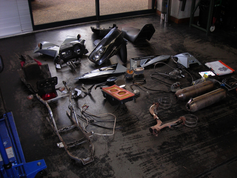
So here's the pile of parts as received:
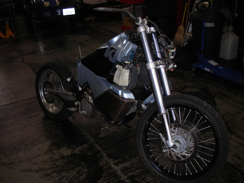
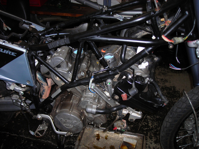
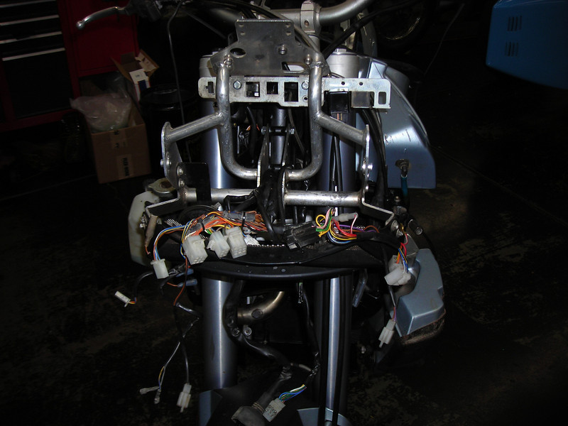
And the big chunk, generously made into a roller by the seller:
The bike was described as having a motor problem, "a noise" as well as a charging system issue. Stator and cam chains diagnosis, possibly with the flywheel loose on the crank taper. That was the worst case scenario in my mind, as a wrecked crank taper would be expensive and time consuming.
I figured if I had to rebuild the motor, I'd expect $2k in parts, which would give me a solid bike for less than the cheapest high mile bike I'd seen anywhere.
I heard the motor start and run before I handed over the cash, but without mufflers, so the first order of business was to fit the exhaust so I could listen to whatever noises it made. Of course I could not just slap it together, I had to clean everything first.
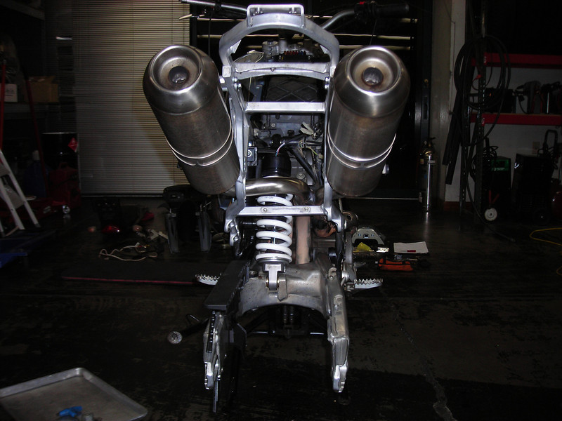
Sodablast to get 89,000 miles of road grime off the subframe and scotchbrite wheel on the buffer to get the pipes shiny again. Sort out missing hardware and gaskets, charge battery, and fire it up!
Sounded good! OK, pretty rattly. And if it failed to start, like it did before I remembered to turn on the fuel tap, it made a big clack when it came to a stop off the starter.
Lets see what's in there then, shall we? This looks suspiciously like a fried regulator connector.
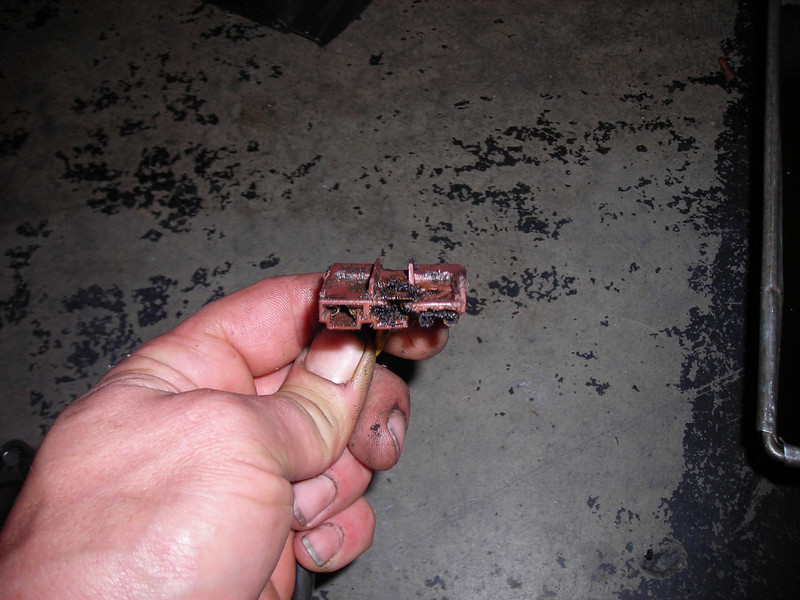
Well well, I've read about this...
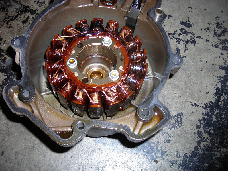
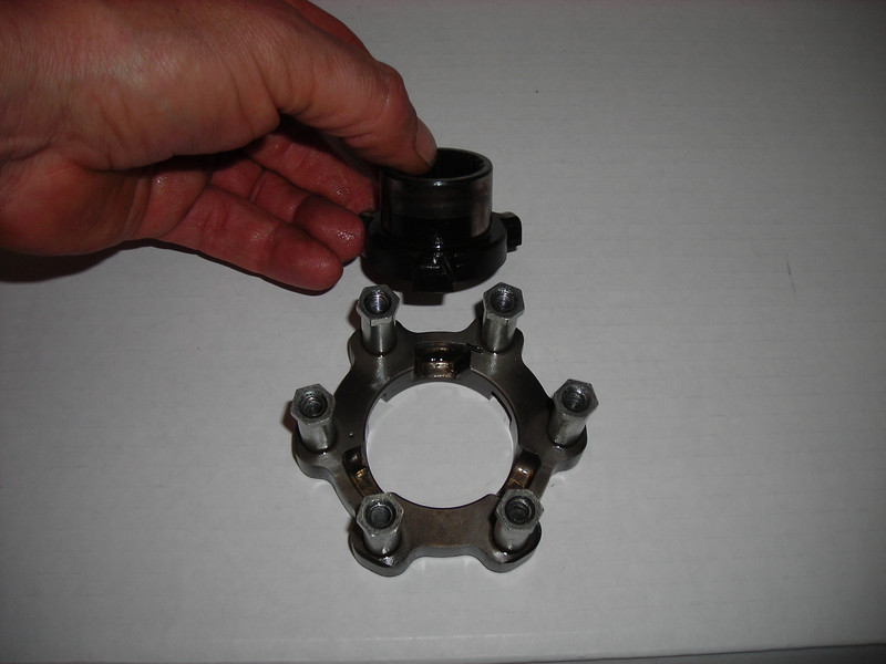
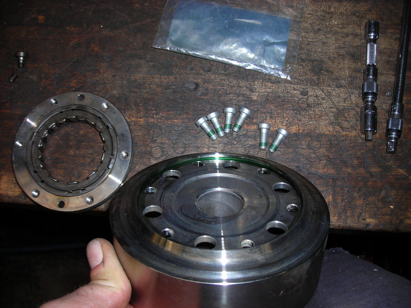
All six bolts loose and coming out..
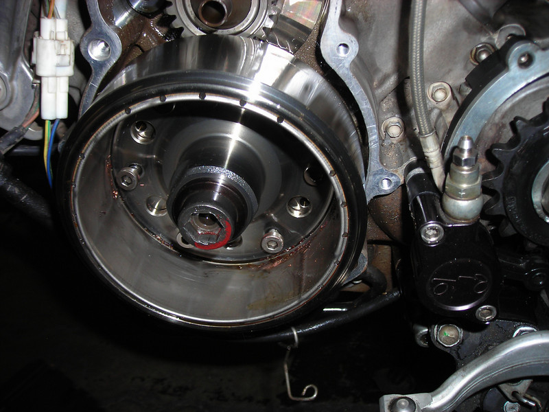
But good news, the flywheel is tight on the crank!
Look Ma, no key!
So this is an early early motor, from what I've read. Also has the old school non-torque-limiter starter drive.
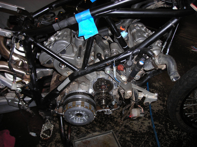
So now I needed to decide if I would just throw a stator at it and ride for the minimum investment, or go big. I read here at OC and over on the HOW for hours, debating pro and con, making parts lists and figuring out the cost. I decided it would be foolish to go in part way and decided to do the timing chains at a minimum, with a leakdown test to determine if the top end came apart. So I stripped the motor down to the point required to swap chains.
Coming apart...
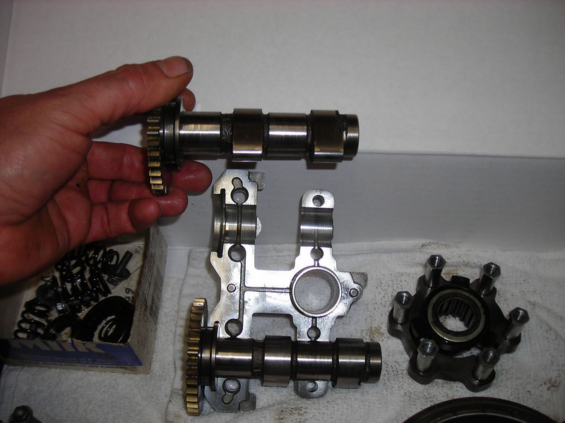
Cams look pretty cherry and lash is only a little out...
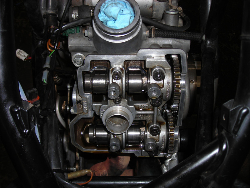
Tappets look good...
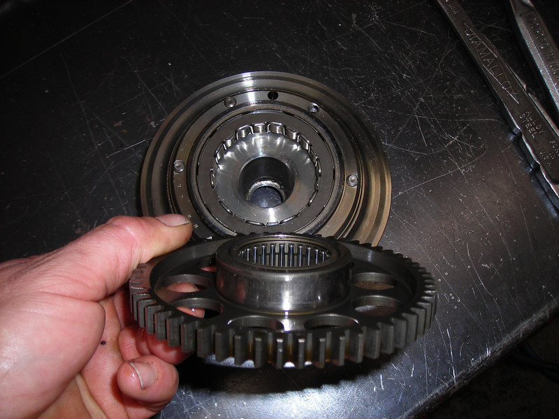
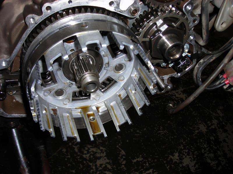
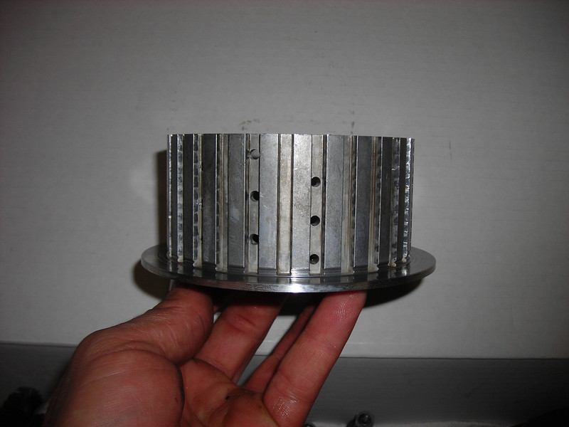
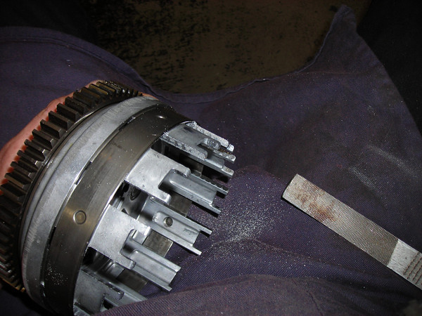
Ooh, that's not so nice. The clutch basket is seriously groovy!
Cam journals had some light scoring and the caps showed some wear. Little nervous about clearance on the outer journals...
My camera SUCKS at macro shots, so these pics don't really show much, but the booster ramps were ugly.
The bearing fell out of the pressure plate...
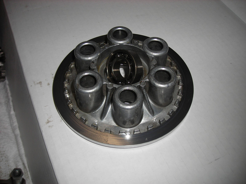
The clutch hub was also pretty worn and had two grooves at the base from the belleville washer, installed upside down.
Note the Feliciani mod!
I hadn't figured on clutch replacement when calculating parts costs. Stupid, eh? It looks like the clutch, excluding plates, is about $900. Lucky for me the plates were all like new, and I can deal with the worn parts for now.
Leakdown results coming up next. 89,850 miles.
OK, so cold leakdown tests don't really tell the whole story, because everything changes when things heat up and parts grow. But hey, this motor is already in pieces!
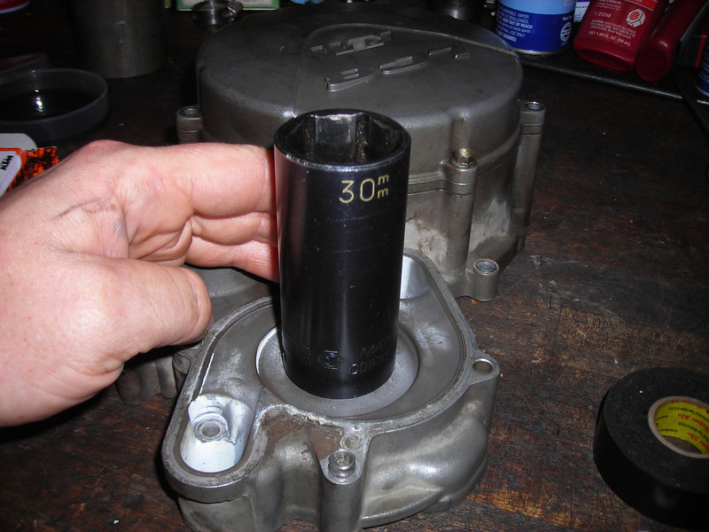
First I had to get the plugs out, and of course none of my many sockets fit. So I turned one down in the lathe to fit. Front jug first...
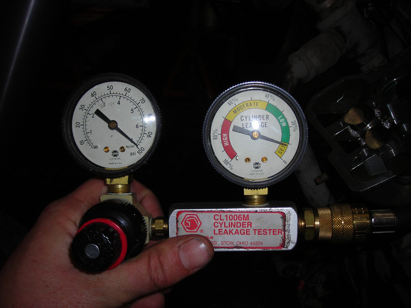
Woo hoo! For those of you that don't know what you're looking at, the gauge set shows inlet pressure on the left and percentage of leakdown on the right, or how how much of that 100 psi the cylinder is holding. 92% here, or 8% leakdown, which seems to me to be a GREAT number for a 90K motor cold. None of it leaking past the valves, just the rings.
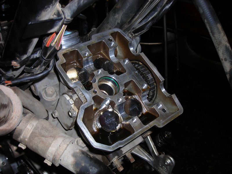
Now for the back hole:
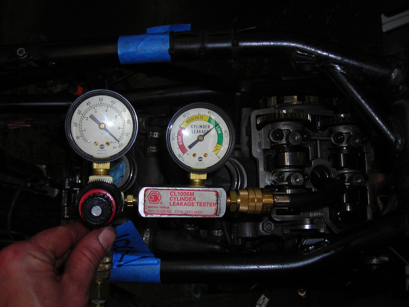
Ooh, not so good. And I can hear the air escaping past the intake valves. I shot some solvent down the port and it gushed right out. See the bubbles?
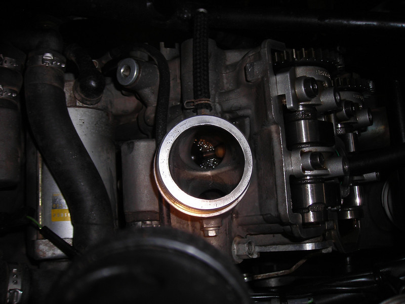
Fortunately, there is a trick here to make sure that the valves are seated properly. There could be a little chunk of dirt or carbon on the seat. Grab a soft drift (I use a brass punch) and whack the top of the bucket, just hard enough to pop the valve off the seat. The air pressure in the cylinder (still connected to the leakdown set) will blow any junk off the seat and give you another reading... like this:
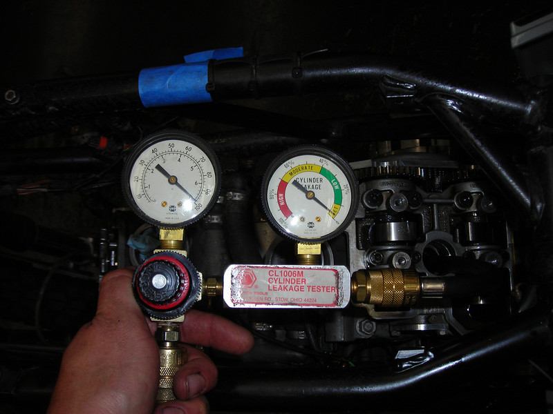
Yes, that's 2% on a 90,000 mile KTM. I am happy and I'm not taking the motor any further apart.
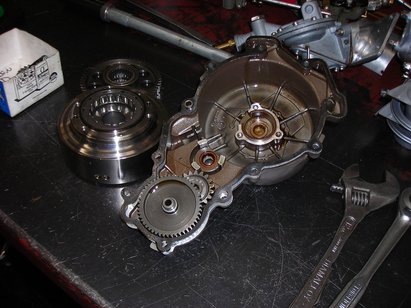
Here's what $750 worth of KTM parts looks like:
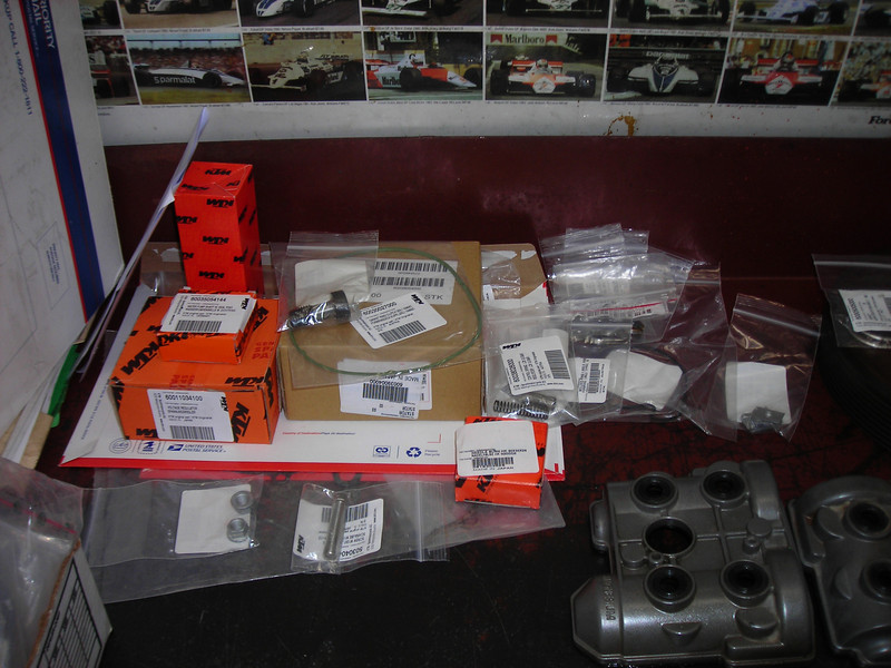
That's a new stator, regulator, timing chains, clutch hub bearing, upper chain needle bearings, chain guides, and gaskets/misc seals.
Ouch.
Also includes some hardware... new chain adjuster bolt to replace the seized one and some oil tank mounts.
Here are the new and old chains:
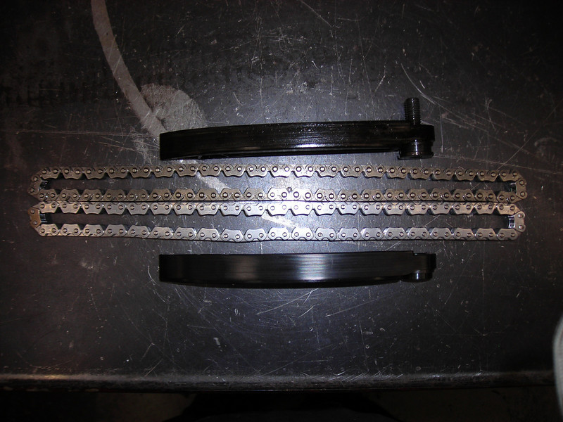
Can you see a difference?
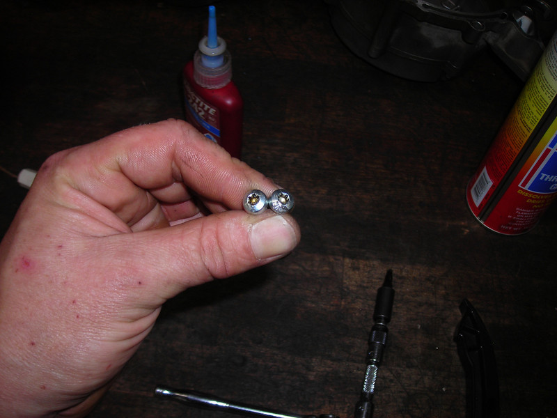
On to the repairs. Here's the new flywheel bolts and Loctite 648.
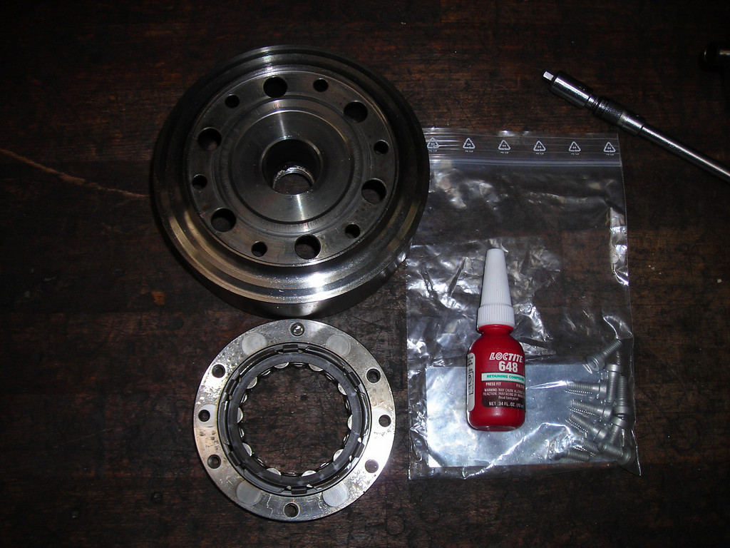
Interestingly, the book says to lay down the 648 on the mating flange as well as on the bolts. This must be to eliminate any movement between the two parts. Also, the book calls explicitly for 12.9 grade bolts, but I got the 10.9 bolts in my order.
Meh.
I hope I haven't screwed the pooch here, but I gotta think this problem is from bolts coming loose, not from bolt strength. I put in the 10.9 bolts.
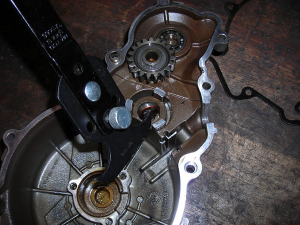
Getting set to put the chains in, I had a close look and saw serious rub marks on the bearing retainer screw shown here.
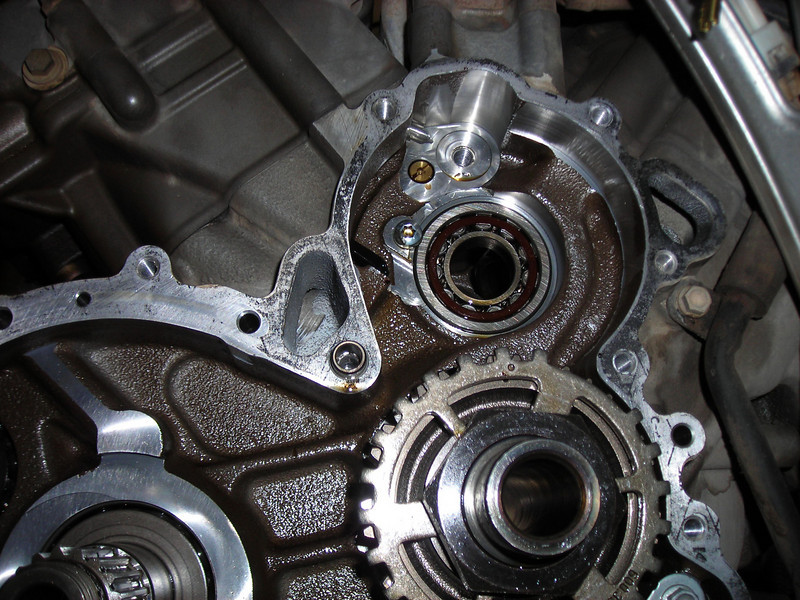
The left side screw had just a touch mark on it, here they are together in harmony:
I filed off the rub marks and put it together. Here's a look at how far away the chain is from the retaining screw, and I'm leaning n the chain to push it towards the screw.
That's the left side, where the tensioner is on the bottom and the rub mark is on the top. To me, this means that the mark is made by the drive side of the chain, the one that is supposed to be taut from the drive of the crank. It can only be loose on off-throttle moments and the tensioner is supposed to take up that slack. Apparently there are times when the tensioner does not live up to its name.
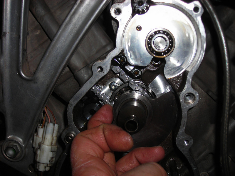
Speaking of which, here is a tensioner:
I've heard of folks having trouble with new tensioners not pumping up quickly (resulting in a noisy new chain set) so I decided to prime them as shown above. Simply drip oil into the open end and operate the plunger until it stops taking in oil. Pre-filled. Yay.
BTW, these are the old units, I didn't buy new.
Another brief note on the whole "noisy chains - lame tensioners" issue. As I primed the tensioners, I reckoned that one faces up and on faces down. There is a ball valve that retains the oil in the body of the tensioner. The other end is closed and cannot possibly leak out oil. So the one on the right side, which has the open end facing up cannot ever bleed down. The one on the right side (behind the oil tank) has the ball valve facing down and can leak out the oil over time while sitting. So it is interesting that the worse chain wear seems to happen on the right side. Gravity. Must be gravity, somehow...
Getting ready to button up the left side and changing the oil seal in the case cover. Totally weird system of breathing, the balance shaft is hollow and open on the end with the seal (which leads to the vent into the airbox). The opposite end of the balance shaft is closed, but the counterweight is drilled with three holes down to the center hollow. These three holes spin around at crank speed and are the only route for case pressure to vent to atmosphere. I wish I took a photo of that. There are two vent pipes from the front head to the oil tank, but the oil tank isn't vented to atmos. All the venting goes out that seal in the stator cover, through that little hole. Surprising.
So this motor had a problem with oil puking out of the vent tube into the airbox, and it was because this seal was dried and broken. Maybe the idea of the three spinning vent holes is to centrifuge out any oil from the breather pipe, and if the end seal fails, the vacuum in the airbox pulls in oil from the stator side? 
More seals. Here is the clutch pushrod seal. Note the updated steel rod.
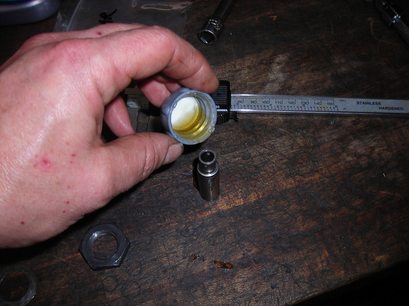
Next I pulled out the clutch oil jet. I was marked 30 for .30 mm.
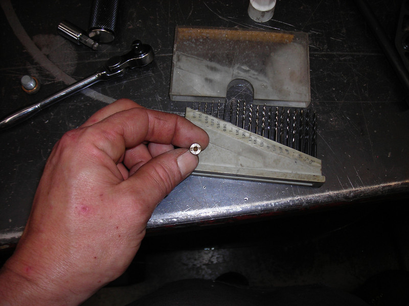
But never trust a jet's markings... I got out the jet drill kit to find what size it actually was, and it measured .55 mm. Cleaned it and put it back.
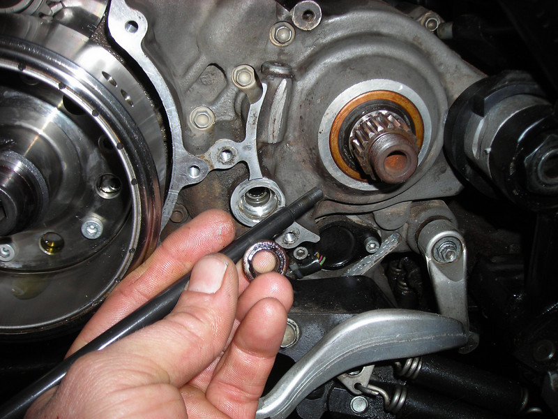
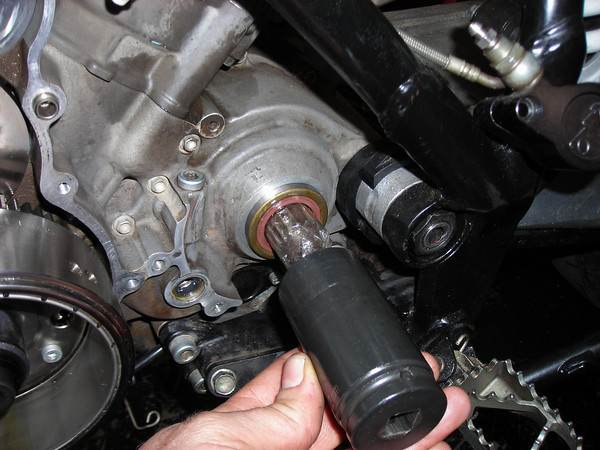
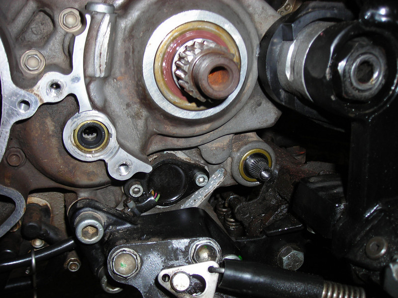
Next I changed the countershaft seal. There is no shoulder behind it so you can use a punch to push one side in until the opposite side pops out, then hook it and yank it out.
BTW, the splines on that countershaft were BARELY worn. Very very good news. I've seen Honda Hawk 650s with wasted splines at less than 50K.
New one going in. I use whatever socket is handy that has the right diameter to push on the seal OD. Note the condom over the splines to prevent nicking the seal lip. (Actually a length of packing tape, but a condom would probably do.)
THere was a second pic of another socket with a larger OD, to make sure the seal only went flush. With no shoulder behind it in the bore, you could easily push it in too far or get it cocked, so use care.
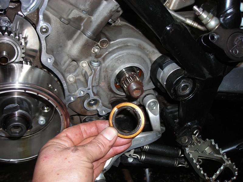
Next up is the shift shaft seal. I'd been warned to replace this it and it became obvious why when I got the shaft out.
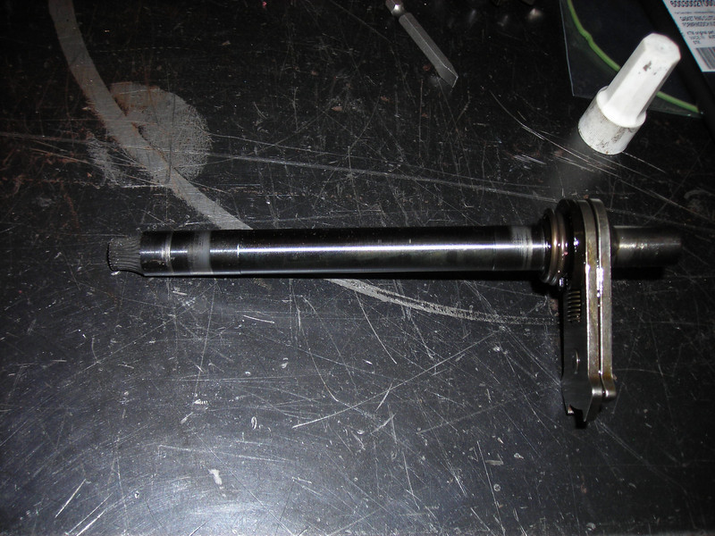
Hard to see with my crap macro lens, but there is a groove around half the seal diameter and nicks on the surface from prior mishandling. See, to properly change this seal you need to pull the shaft which means pulling the clutch basket on the other side. You can try and squeak the seal out without withdrawing the shaft, but you risk leaning on the seal surface when you pull out the seal. As happened here. So the new seal was damaged sliding over the nicks on the shaft. Leak.
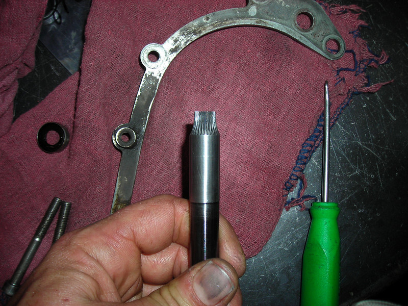
Quick fix, polish out the damage on the lathe. Or careful fettling with a stone and scotchbrite if you don't have your own in-house machine shop.
Almost like new, but not perfect. I'll put in a new shaft if need be when I get around to buying that sweet CJDesigns basket.
All new seals on the left side! I even bought a new o-ring for the gear position switch, but ignored it for now. It was $0.32. Best KTM deal ever.
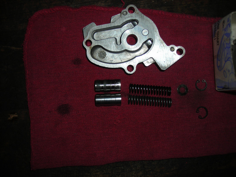
Here is the oil pump, which was my next target. From the OC and HOW record, it seems the pressure pump relief spring can wear out, and I've read something about a piston update. I bought a new spring and piston. Here they are:
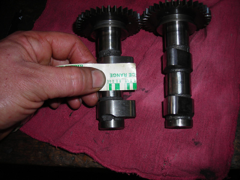
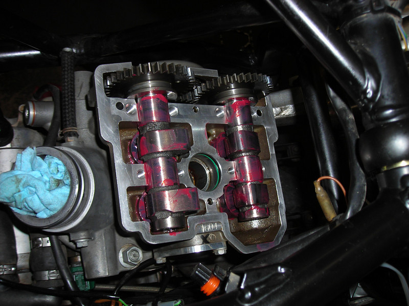
So I was worried about the cam journals. You may have noticed that the 950 cams do not have a journal at the far end. They have two bearings, one next to the sprocket and one between the cam lobes. The cam lobe on the end takes what you could call single shear load, meaning that there is nothing to support the far end of the cam. The outer lobe's work is all taken from one inboard bearing.
This 950 had lash that was .002" big on the outer lobe. And marks on the cam and journals that indicated wear. I was worried that the cam caps were wasted.
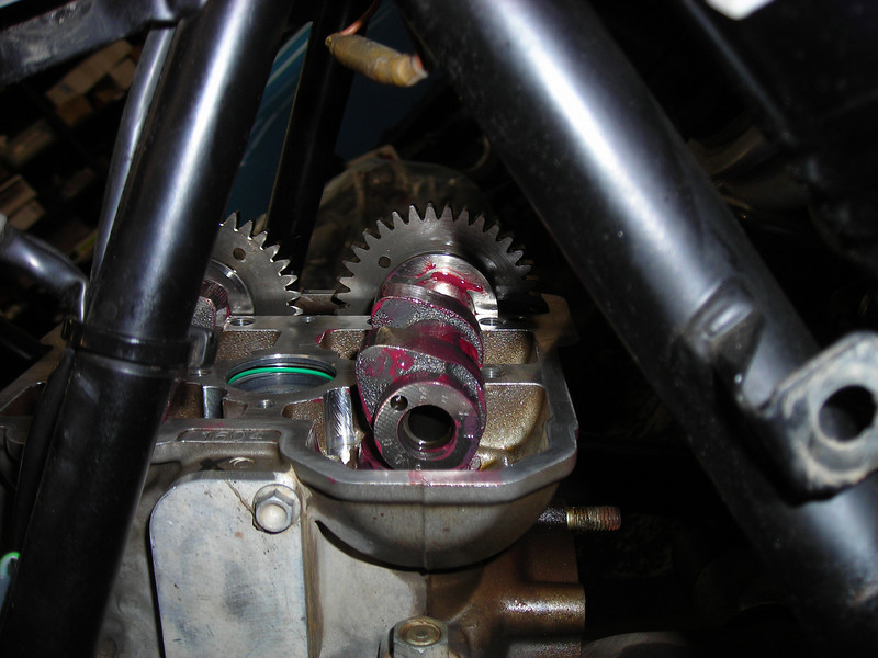
So I followed the book and used plastigauge to check the cam journal clearances.
Despite the appearance of a problem, the actual clearances were right in the middle of the specs.
We are pretty close to a finished motor here and not so much left to show.
I vacillated on changing the water pump parts, but ordered them anyway. Late in the game, I pulled the oil filter and drain plug. I found (surprise!) that the bike had a Scott stainless oil filter and that there was a very small amount of coolant in the oil.
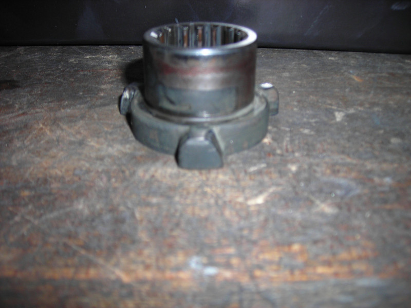
I pulled the water pump shaft from the clutch cover and found this:
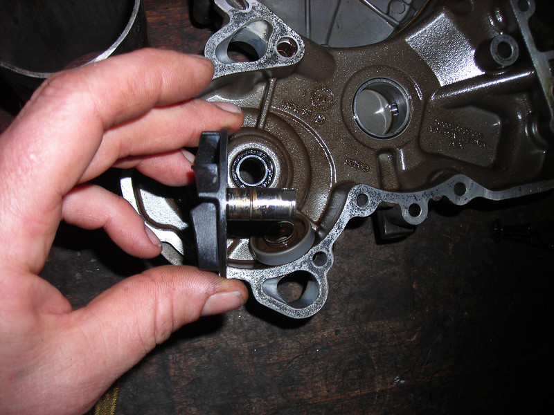
The pump shaft was seriously grooved. Surprise?
Not really.
Next up...
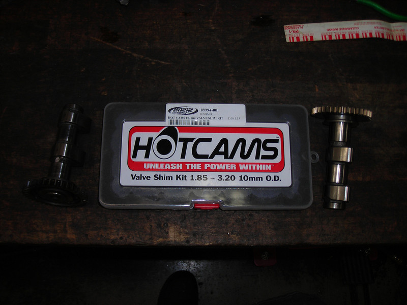
Where was I? Skipping around a bit it appears. The last pic was of the box of shims I bought from Hotcams, and I suppose it wasn't really necessary. There was only one valve that was truly under spec and I could have just ground the shim a couple of thou.
But I'm used to working from big boxes of shims and I wanted to get all 8 spot on in the middle of the spec. (I really should have taken more pics here). Sorry if this is a wordy post...
Two things I learned here:
1) The 9.48 mm shims work fine, because that is what was in it.
2) The .05 mm range in the kits is .002", and I'm an idiot for not figuring that out ahead of time.
See, I needed to make changes from .001" to .003" to get to my middle target of 6 and 10 thou. Off to the surface grinder I go.
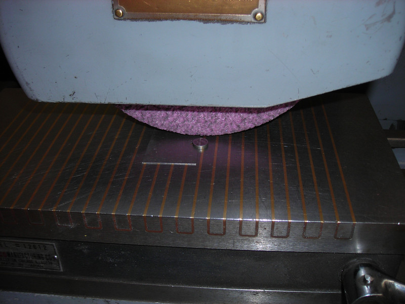
That's what you do when you need to make a shim smaller by .025 mm or .001". Put it on the magnetic table and clip off two passes at 5 tenths each.
Going back together...
I use Redline assembly lube in all my motors, though I go sparingly in the bike motor just because I don't know how it affects a wet clutch.
I must admit to being disappointed with my lash job, and if this were a customer motor I would have gone back and reshimmed it. Even though I cut 3 shims down to within a few tenths (tenth, short for ten thousandth = .0001") of my calculations, I still ended up slightly tighter than I wanted. I wanted 6 and 10 and half were 5 and 9. Oh well, that's still in spec and it won't make any difference.
Really hard to see the alignment mark on the rear cam through the frame, eh?
Maybe I should have read up more about the spreadsheets and tables for shim sizes I've seen here. But it is usually just straight math. Measure the lash, measure the shim, calculate the difference and put in the new shim at that size. It's especially straightforward with shim under bucket designs like this. Not like a Bugatti with a finger follower that slides across the top of the shim.
I ordered a new pump kit even though there were no symptoms showing. Here is what you get with the simple seal/shaft kit, for about $40.
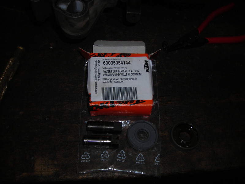
The old shaft and seal are in the pic but again I apologize for my crummy camera. Can't hardly tell new from old.
The new shaft has a black finish that looks like a hard coating. Otherwise the same.
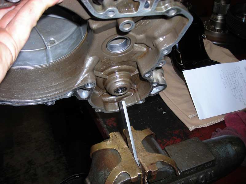
I really didn't want to make a tool to hold the impeller, and the manual describes how you can leave the impeller on and knock the shaft out from the inside. Take off the inner circlip and tap-tap, the shaft comes out.
Hold the shaft in a vise and remove the bolt, then...
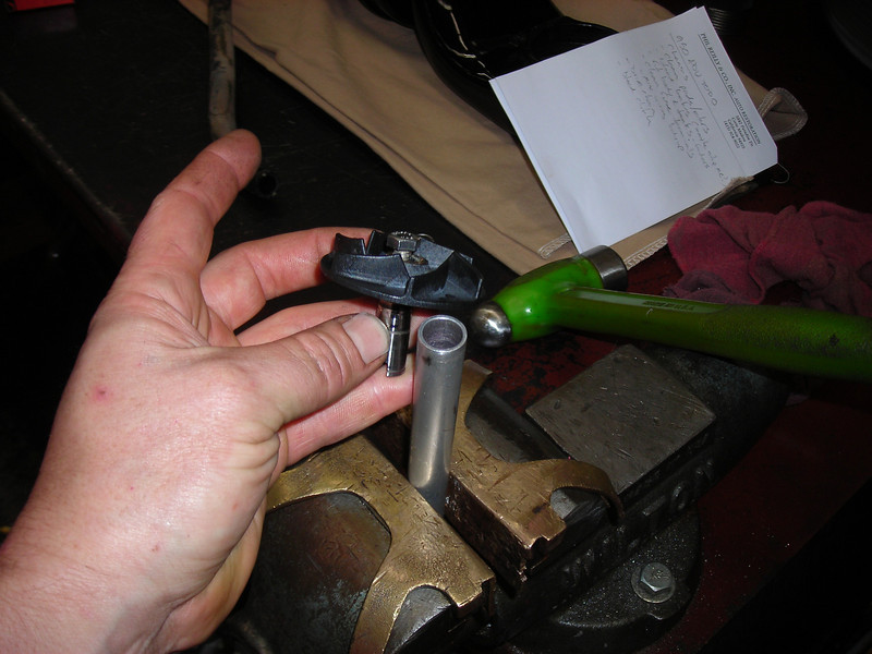
Find a piece of tube that the shaft fits closely. Put the shaft in the tube, screw the bolt back in a few threads, and tap the shaft out of the impeller with your favorite hammer.
I bumped the new seal into the case with an appropriate socket...
How to hold the impeller when you torque the bolt back in? I pushed the impeller onto the new shaft, then the shaft into the bearings. I found a piece of scrap stock that fit the drive tang in the shaft, and clamped the stock in a vise. Then I set the sidecover over the stock, in the tang, to keep the shaft from turning while I torqued the bolt to 10 Nm.
No special tools required!
I had been avoiding the clutch. It all looked ugly, and I had decided to tough it out and not replace any parts, aside from the basket needle bearing, which looked a little suspect with color.
In my business, you can't always buy new parts. It's surprising sometimes how often you CAN buy new parts for 80 year old cars, but lets just say they don't make them like they used to. Sometimes you are better off fixing old junk than buying new junk.
Here is my very worn out booster hub...
I was determined that I could fettle this to make it work better. I looked at the wear on the mating faces, I thought about how I could remove metal and take the shape back towards new. Maybe I'm an idiot, because the new booster set is under $200.
I took it to the bench grinder anyways.
That's the setup. I roughly took the ramp surface down on a tool grinder until it was close to uniform. Then I did some hand work with an air tool and a 2" 120 grit sanding disk, eyeballing it.
Then I got my calipers and measured the width of the dogs and further massaged the ramps.
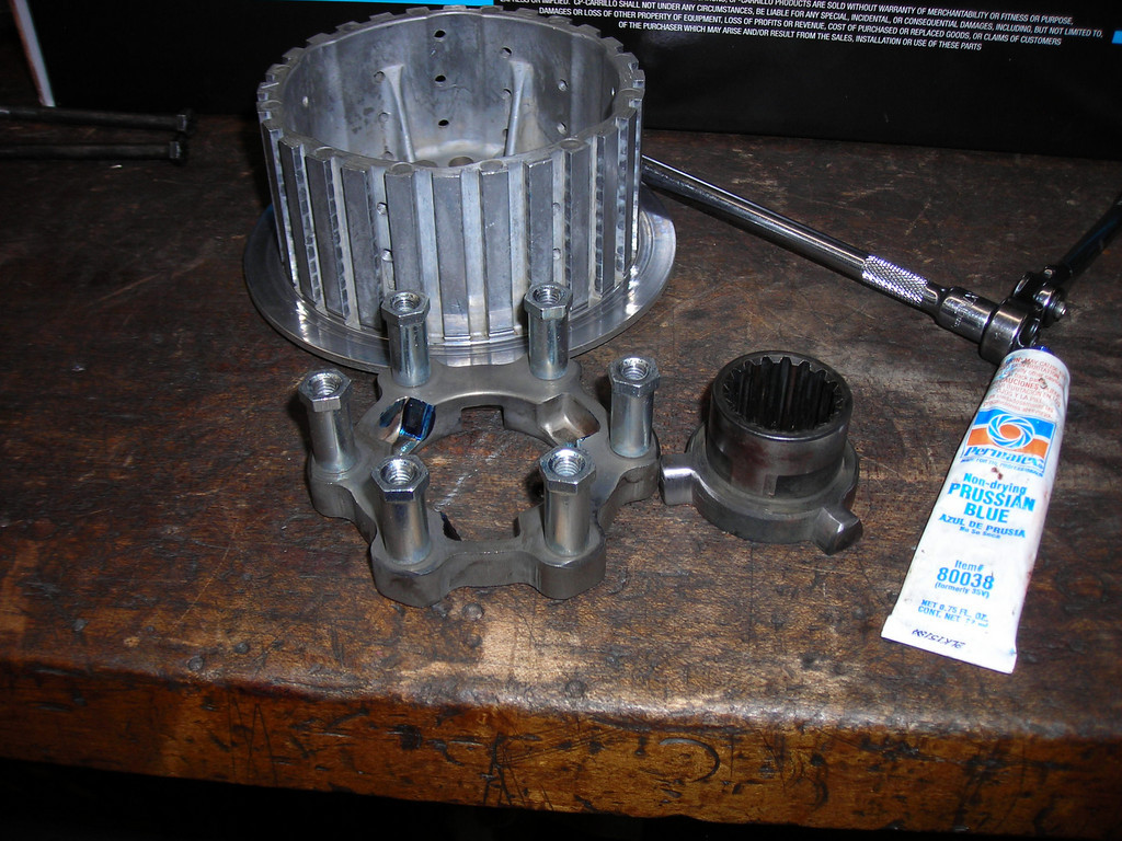
I used prussian blue to work the parts together and judge where the contact was, then worked the surfaces some more.
In all I might have removed .020" from the ramp surface, but the parts had something like .100" slop before hand, so .120" can't make a big diff, right? 
Then I tackled the grooves in the basket. Find the best file for the job... stroke stroke stroke.
This took a while. And in the end, I don't know if it will make a whit of difference.
I cleaned up and assembled the clutch.
All of the plates measured like new.
I bolted up the slave cylinder and operated the lever and was amazed at the travel... the clutch disengages something like a quarter inch! Any clutch drag has to come from stiction related to oil type.
Gah! I'm running out of stuff to show!
I meant to put this in the last post though...
The only bit of cosmetics so far!
Now that the motor is sealed up and running, I wanted to look through the wiring harness and clean up any corrosion in the various connectors.
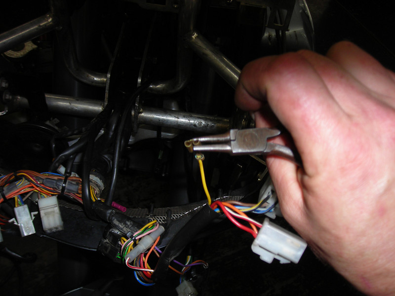
The first item to look at was the starter solenoid, which lives down low in the creek, so to speak. I was just going to remove the battery connections, clean the terminals, apply some dielectric grease and refit.
But when I removed the main battery cable, a part fell off the solenoid! All of the power for the bike's systems comes off the main battery post of the solenoid, through a 30 amp fuse. There is a ring terminal under the cable with a blade connection to the fuse terminal. This is a very thin blade and it was corroded through.
What to do? There was not enough of a stub to solder a repair to, so I tried taking apart the solenoid. Easier imagined than accomplished.
Then I realized that I could just wire a ring terminal under the battery connector, with an inline 30 amp fuse and stick a spade terminal into the far side of the original fuse holder. Brilliant! Except I didn't have an inline fuse holder. So I got out the exacto knife and cut a hole in the side of the relay to expose the fuse holder's hot side, then soldered a link to it. Ghetto fab at its best. Here it is:
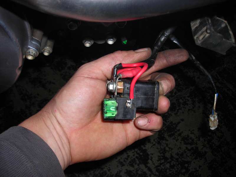
This is a very temporary fix and I'll replace the solenoid before I go anywhere. (although I did find an appropriate inline fuse since then, and I might be tempted...)
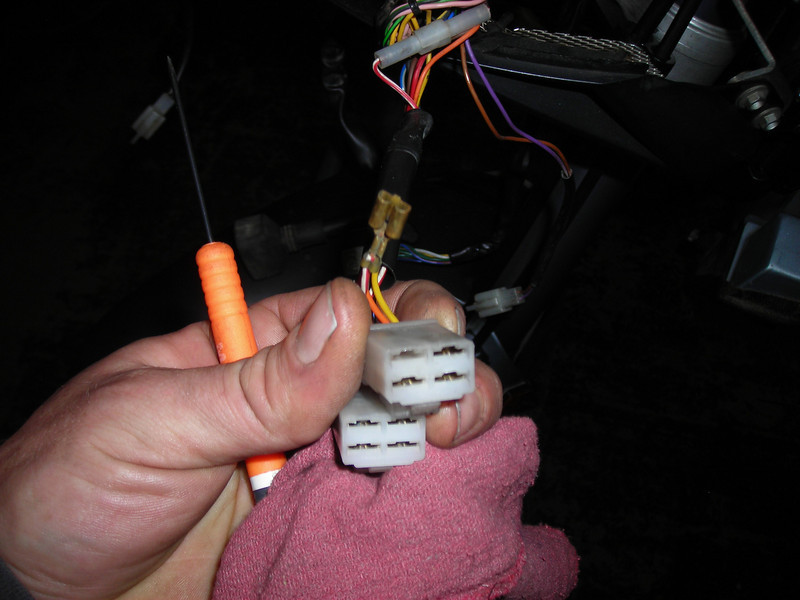
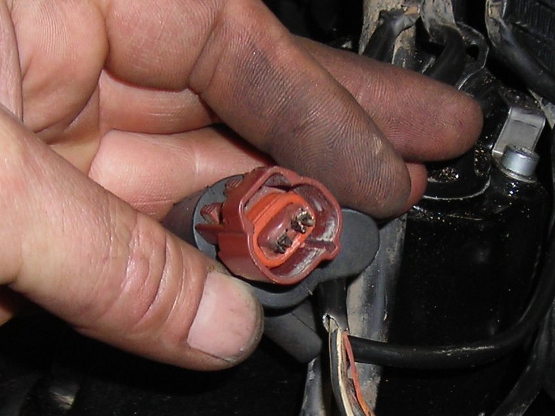
Next I went after all of the plugs under the headlight.
All these plugs are exposed to road spray and were moderately fuzzy with green corrosion. These molex-type plugs do not have o-ring seals, unlike the coil plugs or the starter solenoid and fuel pump connectors.
Here is a plug from the secondary starter relay, with one terminal removed for some love...
Here is my kit of connector love...
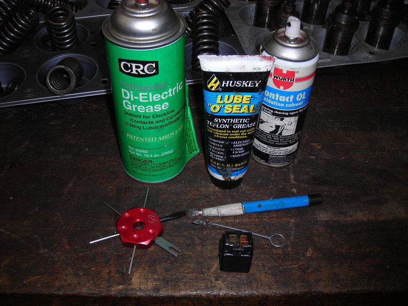
What we have is (L to R) a can of dielectric grease, a tube of much thicker and sticky dielectric grease, a can of contact cleaner (specially intended for improving conductivity), bottom left, a tool for removing connectors from multi-plugs, and some small wire brushes for cleaning terminals.
The goal here was to make sure that the main systems were reliable: clean connections, no hidden chafed wires, and water resistant terminals for long term happiness.
The routine was to to remove one spade terminal at a time, using the tool shown above to release the tang inside the plug. Clean the corrosion with the OL spray and brush, dry with compressed air, then squirt with the spray dielectric grease. Then I squeezed each spade terminal with small pliers to make a tight connector fit, and tweezed the tang back out to secure it in the plug. When all the terminals in one plug were serviced, I smeared some of the sticky dielectric grease over the spade terminals and pushed the plugs back together.
Squeezing the terminal for a tight fit...
Here is one of the two diodes for the starter system, very green and fuzzy!
This bike has no sidestand switch and no clutch switch, but I haven't looked to figure out how that affects the secondary starter relay and the diodes. I had an erratic symptom where it would not fire the starter motor, random clicking under the dash when I turned the key or the kill switch. Hoping I sorted that by cleaning the connectors.
After I serviced the plugs under the dash, I went to put the headlight back on, but noticed a ball of tape on the light's wiring. I peeled it off to check it out, fully expecting some crummy repair, but check this out...
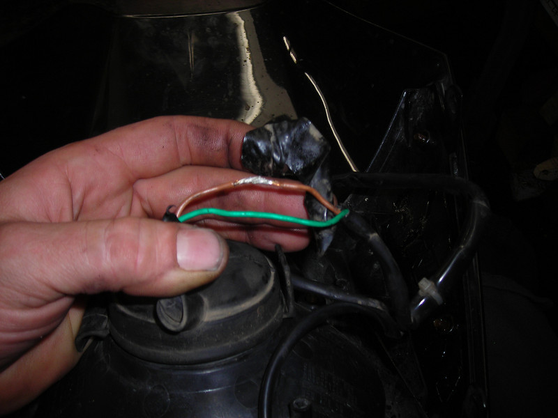
A very nicely soldered joint! Hooray!
Nicely done, Turkish
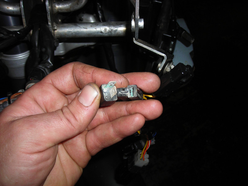
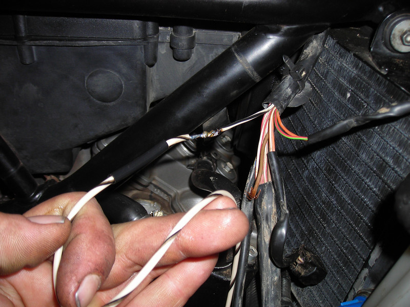
I knew that the fan thermostat plug was roasted, but I didn't worry about it. Here it is...
What I found when I went to repair it was that the wires were melted all the way up to where they joined the main harness.
I should have looked into this before I did the motor work (it would have been easier before refitting the carbs). I had to pull the wiring out of the frame far enough to assess the damage and cut it out. Very lucky that it stopped before reaching the main bundle.
Here is where I cut the wire and soldered in a replacement.
Since the plug was melted and the insulation burned off all the way into the plug, I crimped two small terminals on that would fit the small pins on the temperature sender. I ran an extra length of wire so that I could put a manual fan switch in, but ran out of energy before I could decide on where to mount the switch.
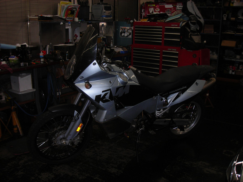
After a long day and somewhat discouraged by the wiring, I wanted to put the body and tanks on so I could call it semi finished and get a feel for the end product.
Man, fitting the tanks and front panels is a pain!
I didn't finish but got it together enough to get a sense of how the bike looks completed.
WOW. It is big.
I've spent a few weeks working on the bike with no body and it seemed so very compact and small. Jesus the tanks make it big!
All hail the big KTM:
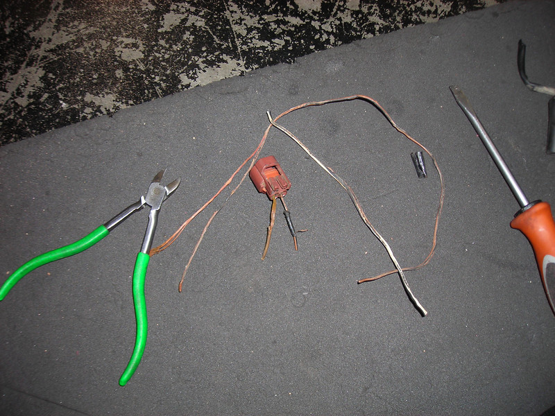
I decided that I could not live with not being able to tune the idle screws while running, but choked at the $100 cost of Flexjets. I had cable, I had jets, and I had a lathe. So I spun up some adapters.
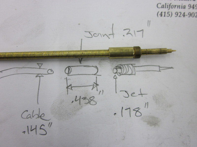
And did a little silver soldering...
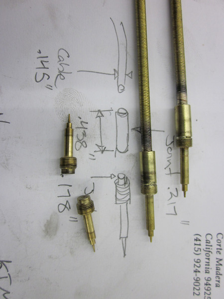
Those other two screws are Honda VTR1000 superhawk parts. Keihin CV carbs on both, but the KTM screws are longer with a different tip.
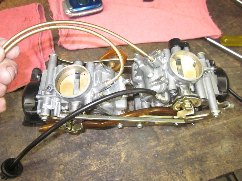
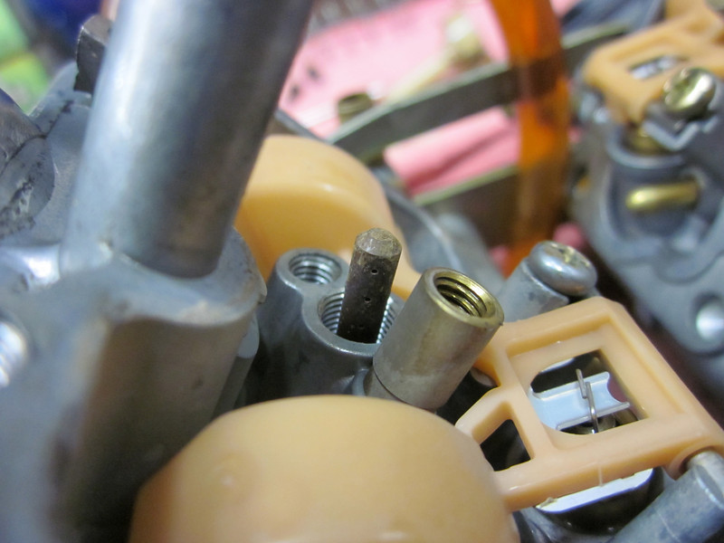
It took longer to fit the cables through the airbox than it did to make the parts.
I cleaned up all the orifices. This main jet emulsion tube was nasty.
I moved the clip to the third slot and I changed the float height to 4 mm from 3 mm, based on what I could scoop out of the 10,000 jetting posts here. Synch'd with a car-type air meter.
It idles better and has better response, pretty crisp off idle now. But it still sounds rough at 1400 RPM and it lacks grunt below 5000. I need to shut up and ride (as suggested), then maybe make another change. Stock pipes, remember, and stock paper filter, no pre-filter.
Disclaimer: The information contained on this page and on this site is condensed from the combined wisdom of the members and contributors of the Orange Crush Forum. The contributions are reprinted here exactly as posted by the contributors. The spelling, syntax, grammar, etc have purposely not been corrected in order to retain its original flavor. The contributors are from throughout the World, and English may very well not be their native language. Don't be an ass and complain about the lexicon. It is mostly subjective, with a little objectivity thrown in for seasoning, based on the experiences of the contributors. Use this info at your own risk. The site owner is not responsible for its accuracy or validity. None of the procedures described should be taken as recommendations by anyone. Take anything you read or hear anywhere, but especially on the World Wide Web with a very large dose of salt. The cognoscente is a skeptic.